Milling Machine Guide: Machine Types, Cutting Tools, Operating Methods and Manufacturing Uses
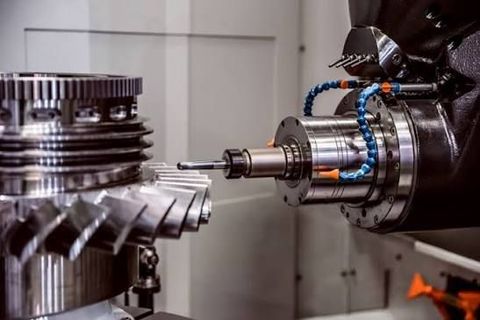
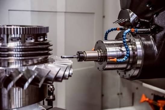
A milling machine is a manufacturing machine used to remove material from a workpiece with a rotating cutting tool. It can produce flat surfaces, slots, grooves, holes, curved profiles, and complex shapes in materials such as metals, plastics, and certain composites. Milling is widely used in manufacturing because it allows components to be shaped with controlled dimensions and repeatable machining operations.
Context
The development of milling machines is closely connected to the growth of mechanical engineering and industrial production. Early machines were primarily mechanically operated, while modern equipment may use computer numerical control (CNC) to coordinate tool movement, spindle rotation, and machining sequences.
A milling machine generally consists of a base, column, worktable, spindle, cutting tool, and mechanisms for moving the workpiece or tool. The exact arrangement depends on the machine design. Some machines are operated manually, while others use programmed movements to produce complex components with limited direct intervention during machining.
Milling differs from processes such as turning because the cutting tool usually rotates while the workpiece is secured to a table or fixture. The interaction between the rotating cutter and the material removes small chips, gradually forming the required geometry.
How a milling machine works
The workpiece is secured to the machine table or an appropriate fixture. A cutting tool is mounted in the spindle or tool holder, and the operator establishes the required spindle speed, feed rate, cutting depth, and tool path.
During machining, the cutter removes material as it moves across the workpiece. Coolant or cutting fluid may be used when appropriate to manage heat, reduce friction, and assist chip removal. The finished shape depends on the cutter geometry, machine movement, workpiece setup, and machining parameters.
Importance
Milling machines play an important role in producing components used in industrial equipment, transportation, electronics, construction machinery, and general manufacturing. They can create features that are difficult to produce through simple drilling or sawing, including pockets, keyways, precision slots, and contoured surfaces.
Manufacturers use milling to prepare machine housings, brackets, plates, fixtures, gears, mould components, and other parts. The process can also support prototype development, repair work, and small production batches where different component geometries are required.
The accuracy of a milled component depends on several factors, including machine rigidity, tool condition, workpiece stability, material properties, temperature, and operator technique. Poor setup or an unsuitable cutting tool can result in surface defects, dimensional variation, excessive vibration, or premature tool wear.
Common milling machine types
Different milling machine designs accommodate different workpiece sizes, geometries, and production requirements.
Vertical milling machine: The spindle is oriented vertically, making it suitable for many face-milling, slotting, drilling-related, and pocket-machining operations.
Horizontal milling machine: The spindle is oriented horizontally. These machines can accommodate cutters and setups suited to certain heavy material-removal and production tasks.
Universal milling machine: This design provides additional table movement or angular adjustment, depending on its configuration, for machining features at different orientations.
Turret milling machine: The spindle head can be adjusted to support different machining positions. This arrangement is common in versatile workshop equipment.
Bed-type milling machine: The worktable is supported on a substantial bed, providing a rigid structure for machining larger or heavier components.
CNC milling machine: Computer-controlled movements coordinate machining operations according to a programmed tool path. Depending on the machine, several axes may be controlled simultaneously.
Milling machine types at a glance
Machine type | Main characteristic | Typical applications |
|---|---|---|
Vertical | Vertically oriented spindle | Pockets, slots, flat surfaces |
Horizontal | Horizontally oriented spindle | Heavy cutting, grooves, production machining |
Universal | Additional angular or table flexibility | Angled features and varied setups |
Turret | Adjustable spindle head | General workshop machining |
Bed-type | Rigid bed-supported structure | Larger components and heavier cuts |
CNC | Programmed axis movement | Repeatable and complex component geometries |
The categories can overlap. For example, a CNC machine may also have a vertical spindle, and machine capabilities vary with the specific model and configuration.
Recent Updates
Milling technology continues to develop through improvements in computer control, cutting-tool materials, machining simulation, and production monitoring. Developments from 2024 through 2026 reflect a broader manufacturing trend toward connecting machine tools with digital planning systems and using production data to identify process variations.
CNC automation and digital manufacturing
Modern CNC milling machines can execute programmed tool paths, coordinate multiple axes, and repeat machining sequences. Some machining centres also include automatic tool changers, tool magazines, probing systems, and sensors that monitor selected operating conditions.
Computer-aided manufacturing (CAM) software converts component designs into machining instructions. Simulation tools can help identify possible tool collisions, unsuitable movements, and machining problems before a program is run on the physical machine. Simulation results still depend on accurate machine models, tool information, fixtures, and setup data.
Cutting-tool materials and process monitoring
Carbide tools, coated cutting inserts, and specialised tool geometries are used for different combinations of material hardness, cutting speed, and production requirements. Tool selection depends on the workpiece material, required surface finish, machine rigidity, and the type of milling operation.
Some systems monitor spindle load, vibration, temperature, or tool wear indicators. These measurements can help operators identify unusual conditions, although sensor readings do not automatically establish the cause of a problem.
Multi-axis machining
Three-axis milling controls movement along three linear directions. Four-axis and five-axis systems add rotational movement, allowing certain angled surfaces and complex shapes to be machined with fewer separate setups.
Multi-axis machines are used in applications such as mould production, aerospace components, medical equipment components, and complex industrial parts. Their capabilities depend on the machine configuration, programming, tooling, and workpiece geometry.
Laws or Policies
Milling machines are subject to workplace safety requirements and, depending on the jurisdiction and intended use, machinery design and conformity requirements. These rules may address machine guarding, electrical safety, operator training, maintenance procedures, hazardous energy, and exposure to airborne particles or cutting fluids.
International Standard ISO 16090-1:2022 addresses safety requirements for milling machines, machining centres, and transfer machines used for machining metal and certain other materials. It covers relevant hazards during activities such as installation, setting, operation, cleaning, and maintenance. The standard is a technical reference; its legal status depends on how applicable authorities or regulations adopt or reference it. (ISO)
Workplace safety requirements
Common safety considerations include:
Machine guarding: Appropriate guards and enclosures help reduce exposure to rotating cutters, moving components, and flying chips.
Hazardous energy control: Equipment must be isolated according to applicable procedures before certain maintenance or repair tasks.
Personal protective equipment: Eye protection, hearing protection, and other equipment may be required following a workplace hazard assessment.
Operator training: Personnel need to understand the machine's controls, operating limits, emergency procedures, and relevant hazards.
Maintenance and inspection: Guards, interlocks, electrical systems, fixtures, and other safety-related components need appropriate inspection and upkeep.
In the United States, the Occupational Safety and Health Administration addresses machine guarding through requirements including 29 CFR 1910.212. Other jurisdictions have their own workplace safety laws and machinery rules. (OSHA)
The specific requirements depend on the location, workplace, machine type, and activity being performed. General educational information does not replace applicable regulations, machine instructions, or a site-specific safety assessment.
Tools and Resources
Several technical resources help explain milling machine operation, cutting-tool selection, machining calculations, and equipment safety.
Machining calculators
Spindle-speed and feed-rate calculators help estimate machining parameters from tool diameter, cutting speed, number of cutting edges, and feed per tooth. These calculations provide starting estimates rather than universal operating settings.
Two common relationships are:
For metric units, \(N\) is spindle speed in revolutions per minute, \(V_c\) is cutting speed in metres per minute, and \(D\) is cutter diameter in millimetres.
Here, \(V_f\) is feed rate in millimetres per minute, \(z\) is the number of cutting teeth, and \(f_z\) is feed per tooth in millimetres.
Actual settings must account for the cutter manufacturer's guidance, workpiece material, machine limits, tool engagement, rigidity, and coolant conditions.
CAD and CAM software
Computer-aided design (CAD) software is used to create component geometry and technical drawings. CAM software develops machining paths and generates instructions for compatible CNC equipment. Simulation and verification functions can help identify programming issues before machining begins.
Technical manuals and standards
Machine manuals contain information about spindle limits, tool holders, lubrication, workholding, maintenance, and operating procedures. Cutting-tool manufacturers also publish technical guidance covering tool geometry, material compatibility, and machining parameters.
International standards catalogues and relevant workplace safety authority websites provide information about machinery safety requirements. These sources help distinguish general machining principles from requirements that apply to a particular machine or workplace.
FAQs
What are the main types of milling machines?
The main types include vertical, horizontal, universal, turret, bed-type, and CNC milling machines. They differ in spindle orientation, table movement, structural design, and level of automation. The appropriate type depends on the component geometry and machining requirements.
What cutting tools are used in a milling machine?
Common milling cutting tools include end mills, face mills, slot drills, slab mills, ball-nose cutters, and chamfering cutters. Each tool has a particular geometry and intended application, such as producing flat surfaces, slots, curved profiles, or angled edges.
What is the difference between CNC milling and manual milling?
Manual milling relies on an operator to control machine movements and machining operations. CNC milling uses programmed instructions to coordinate tool movement and other machine functions. CNC systems can repeat complex sequences, while manual machines allow direct adjustment during machining.
What materials can a milling machine process?
Depending on the machine and cutting tool, milling can process aluminium, steel, cast iron, copper alloys, plastics, and certain composites. Material hardness, heat generation, chip formation, and tool compatibility influence the machining method and operating parameters.
What safety precautions are important when operating a milling machine?
Important precautions include using appropriate machine guards, securing the workpiece, checking tool condition, and following the manufacturer's operating instructions. Loose clothing and jewellery should be kept away from rotating components, and chips should be removed with suitable tools only after the machine has stopped, following the applicable safety procedure.